
The press-fit stainless steel clamp insertion depth is a key part of a reliable pipe connection.
The correct depth depends on the nominal pipe diameter (DN), fitting design, and applicable standards. If the pipe is not inserted far enough, the sealing ring may not work correctly. If the installation is not done correctly, the connection may also have poor pull-out resistance.
This guide explains the main insertion depth requirements, installation steps, inspection methods, and special application considerations.
1. Press-Fit Stainless Steel Clamp Insertion Depth Standards
1.1 Main Standards for Insertion Depth
The required insertion depth for a press-fit stainless steel connection should be based on the fitting standard and the actual fitting design.
Two important standards are commonly referenced:
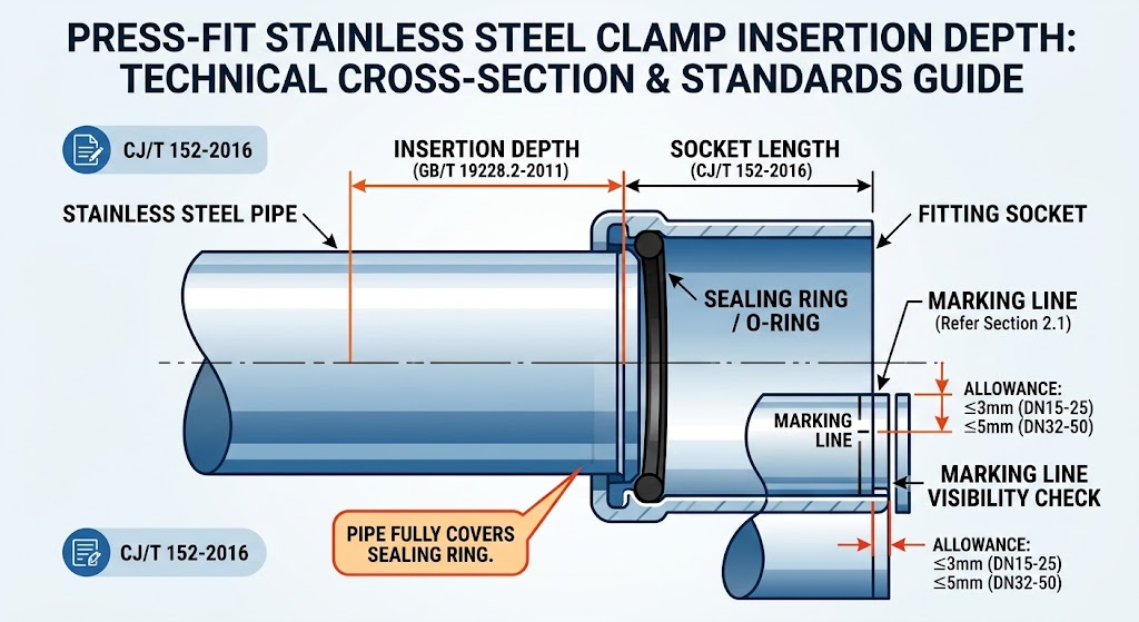
- CJ/T 152-2016, Thin-Wall Stainless Steel Press-Fit and Grooved Fittings. It defines the socket length, which determines the required insertion depth for different pipe sizes. For example, the socket length for a DN25 fitting is 23 ± 3 mm.
- GB/T 19228.2-2011, Stainless Steel Press-Fit Fitting Assemblies — Part 2: Thin-Wall Stainless Steel Pipes for Connection. The pipe must be inserted far enough to ensure that the sealing ring is fully covered. Insufficient insertion can lead to leakage.
The fitting manufacturer’s specification should also be checked before installation. Different fitting designs may have different socket dimensions.
1.2 Insertion Depth for Different DN Sizes
The required insertion depth changes with pipe diameter.
Common engineering values are shown below.
Unit: mm
| Nominal Diameter (DN) | Typical Insertion Depth |
| DN15 | 21 |
| DN20 | 22 |
| DN25 | 23–24 |
| DN32 | 39 |
| DN40 | 47 |
| DN50 | 52 |
| DN65 | 63 |
| DN80 | 68 |
| DN100 | 75 |
These values should be treated together with the applicable fitting standard and manufacturer’s specifications.
For threaded fittings, the thread should be tightened before pressing. This helps prevent movement of the fitting and changes in insertion position after the press operation.
For reducing fittings, each end has its own insertion depth.
For example, a DN40 × DN25 reducing tee may require 47 mm insertion at the DN40 end and 24 mm at the DN25 end.
2. How to Control Press-Fit Stainless Steel Clamp Insertion Depth
Correct insertion starts before the pressing operation.
A simple marking and checking process can prevent many connection problems.
2.1 Mark the Pipe Before Insertion
Use a dedicated marking tool to make the insertion line on the pipe.
For a DN25 pipe, for example, the marking line may be placed 24 mm from the pipe end.
Insert the pipe until the fitting position reaches the marked area.
For DN15–DN25 systems, the distance between the fitting end and the marking line should be ≤3 mm.
For DN32–DN50 systems, this distance should be ≤5 mm.
The marking line provides a simple visual check. It helps the installer confirm that the pipe has reached the required position before pressing.
2.2 Clean the Pipe and Fitting
Clean surfaces are important for a stable connection.
Before assembly:
- Clean the outside of the pipe.
- Clean the fitting socket.
- Remove oil, dust, and other contamination.
- Use anhydrous ethanol or acetone for cleaning where suitable.
If insertion is too tight, clean water may be used for lubrication.Do not use oil or grease unless the fitting manufacturer specifically approves it.Some lubricants can affect the sealing ring or contaminate the connection.
2.3 Insert the Pipe Straight
The pipe should enter the fitting socket in a straight direction.Do not force the pipe into the socket at an angle.A tilted pipe can move or damage the sealing ring. It may also cause uneven contact between the pipe and fitting.After insertion, check the position with a depth gauge when required.
As a general engineering control, the actual insertion depth should be within ±2 mm of the specified value.
For example, when the specified DN50 insertion depth is 52 mm, the controlled range is 50–54 mm.
3. Inspection After Pressing
Insertion depth is only one part of connection quality.
The completed press-fit joint should also be checked after pressing.
3.1 Check the Pressed Shape
The pressed section should have a regular shape according to the fitting system.
For a hexagonal press profile, the finished area should form a clear and uniform hexagonal impression.
Check for:
- Cracks
- Abnormal deformation
- Sealing ring extrusion
- Uneven pressing
If any abnormal condition is found, the joint should be inspected before the system is put into service.
3.2 Use a Dedicated Inspection Gauge
A dedicated hexagonal gauge can be used to check the pressed section.
For example, a DN25 gauge may have a side length of 25.4 mm.
If the gauge cannot fully fit over the pressed section, the connection should be checked and re-pressed according to the fitting manufacturer’s procedure.
The correct press tool and matching jaw are also important. The tool must be suitable for the fitting type and pipe size.
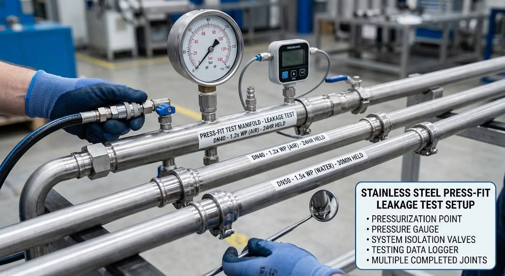
3.3 Perform Pressure or Leak Testing
The completed pipe system should be tested before operation.The exact test method should follow the applicable project specification and system standard.
Common engineering practice includes:
- Water pressure test: 1.5 times the working pressure, held for 30 minutes with no leakage.
- Air-tightness test: 1.2 times the working pressure, held for 24 hours with no leakage.
Testing helps identify sealing problems that cannot be found through visual inspection alone.
4. Special Requirements for Different Applications
The basic insertion depth requirements may not be enough for special service conditions.
Temperature, hygiene, corrosion protection, and installation environment must also be considered.
4.1 Food and Pharmaceutical Applications
Food and pharmaceutical pipe systems have strict hygiene requirements.Insertion accuracy may need to be higher than in general industrial systems.
For these applications, the insertion depth tolerance may be controlled within ±1 mm.
For example, if the specified DN32 insertion depth is 39 mm, the controlled range is 38–40 mm.
Better dimensional control helps reduce unwanted gaps where process media may remain.The sealing ring should also meet the required sanitary standard.
Where specified, FDA-compliant silicone rubber can be used. A typical hardness is Shore A 70 ± 5.
Before installation, the sealing ring may require steam sterilization, such as 121°C for 30 minutes, according to the applicable process requirements.
4.2 High-Temperature Pipe Systems Above 100°C
Temperature changes can affect pipe and fitting dimensions.Thermal expansion should therefore be considered during system design and installation.
Some engineering applications may require an expansion allowance of 0.5–1 mm, depending on the fitting structure and manufacturer’s requirements.
For example, where the specified insertion depth is 52 mm, an installation depth of 51.5 mm may be used when the applicable system specification requires this allowance.
Do not change the specified insertion depth without confirming the fitting design and manufacturer’s instructions.The sealing ring must also be suitable for the service temperature.
FFKM may be selected for demanding high-temperature applications. The actual temperature range must be confirmed with the sealing material manufacturer.The lubricant must also be compatible with the sealing ring and operating temperature.A suitable high-temperature lubricant should be used where lubrication is required.
4.3 Buried and Highly Corrosive Pipe Systems
Buried pipe systems have additional protection requirements.
The pipe surface may require an external anti-corrosion system such as 3PE coating.
Where specified, the polyethylene layer may have a thickness of ≥2.5 mm.
The connection area must be designed so that the protective coating does not interfere with the sealing surface.
For example, if the standard DN100 insertion depth is 75 mm, an increased depth such as 80 mm should not be applied automatically.
Any change in insertion depth must be confirmed by the fitting manufacturer or the applicable project specification.Buried connections should also be inspected according to the project maintenance plan.Special attention should be given to movement caused by soil settlement.
If loosening is found, corrective action should follow the requirements of the specific press-fit system.
5. Common Insertion Depth Problems and Prevention
Several installation errors can affect the performance of a press-fit stainless steel connection.
| Common Problem | Possible Effect | Prevention |
| Pipe inserted too shallow | Leakage or poor pull-out resistance | Mark the insertion depth before assembly |
| Incorrect insertion position | Sealing problems | Check the marking line and depth |
| Pipe inserted at an angle | Sealing ring damage or displacement | Keep the pipe straight |
| Dirty pipe or socket | Poor sealing performance | Clean both surfaces before insertion |
| Damaged sealing ring | Leakage | Inspect the sealing ring before assembly |
| Wrong lubricant | Seal damage or contamination | Use a compatible lubricant |
| Incorrect press tool | Improper press profile | Use the specified press tool and jaw |
| No gauge inspection | Pressing defects may remain | Check with the correct inspection gauge |
| No pressure test | Leakage may remain undetected | Complete the required pressure or leak test |
These problems are often related to installation control rather than the stainless steel material itself.
A clear marking process and proper inspection can reduce installation errors.
6. Tools and Materials for Accurate Installation
The right tools help maintain the required press-fit stainless steel clamp insertion depth.
Common installation tools and materials include:
- Dedicated stainless steel pipe cutter
- Pipe deburring tool
- Insertion depth marking tool
- Depth gauge
- Dedicated press-fit tool
- Matching press jaw
- Hexagonal inspection gauge
- Clean cloth
- Anhydrous ethanol or suitable cleaning agent
- Compatible lubricant, where required
- Correct sealing rings
- Water pressure or air-tightness testing equipment
The tools must match the pipe size and fitting system.
The press tool and jaw should also be checked before use.
Always follow the tool manufacturer’s operating instructions.
Insights
The press-fit stainless steel clamp insertion depth is a basic but critical installation parameter.
It affects sealing performance, pull-out resistance, and the reliability of the finished connection.
For standard applications, the insertion depth should be based on CJ/T 152-2016, GB/T 19228.2-2011, the fitting design, and the manufacturer’s specifications.
Common examples include 23–24 mm for DN25, 52 mm for DN50, and 75 mm for DN100.
Installation also requires proper pipe marking, surface cleaning, straight insertion, and correct pressing.After pressing, inspect the press profile and use the proper gauge. Complete the required pressure or air-tightness test before the system enters service.
Special applications need additional control.
Food and pharmaceutical systems may require ±1 mm insertion depth control and suitable FDA-compliant sealing materials.
High-temperature systems above 100°C require attention to thermal expansion, sealing material, and lubricant compatibility.
Buried or highly corrosive systems may require 3PE anti-corrosion protection and regular inspection.
The exact insertion depth should always be confirmed against the applicable standard and fitting manufacturer’s requirements.
With proper depth control and installation inspection, press-fit stainless steel connections can provide reliable sealing and long-term service performance.