
When installing a stainless steel clamp connection, the pipe end must be prepared correctly. Stainless steel clamp pipe cut standards vary with the connection type, pipe size, and application.
The main points are simple. The pipe cut must be straight and clean. Burrs must be removed. The pipe must keep its correct shape. For grooved connections, the groove must also match the clamp dimensions.
This guide covers the main requirements for grooved clamp, press-fit, and hose clamp connections. It also explains cutting tools, dimensional checks, common mistakes, and special requirements for food, pharmaceutical, semiconductor, and electronic applications.
1. Stainless Steel Clamp Pipe Cut Standards for Grooved Clamp Connections
Grooved clamp connections are widely used in industrial piping. Unlike a simple pipe cut, this connection requires a machined groove near the pipe end.
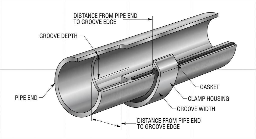
The clamp housing engages with this groove. The gasket sits around the pipe joint and provides the seal. Therefore, both the pipe-end position and groove dimensions must be controlled.
1.1 Groove Dimensions
The required groove size depends on the nominal pipe diameter. Taking GB/T 19228.1-2024 as an example, groove depth, groove width, and the distance from the pipe end to the groove must meet the applicable requirements.
For DN50–DN150 pipes:
- Groove depth: 2.3–2.8 mm
- Groove width: 8.5–11.5 mm
- Distance from pipe end to groove edge: 14.5–16 mm
For example, a DN100 pipe may require:
- Groove depth: 2.8 ± 0.1 mm
- Groove width: 11.5 ± 0.2 mm
- Pipe-end distance: 16 mm
For DN200–DN300 pipes, the groove is larger:
- Groove depth: 3.0–3.5 mm
- Groove width: 12.5–15 mm
These larger dimensions help meet the connection and sealing requirements of larger pipe sizes.
1.2 Groove Position and Surface Condition
The groove should be close to the pipe end. The recommended position is about 10–15 mm from the pipe end, while the final dimension must follow the applicable standard and clamp design.
The groove surface should be smooth. It should not have deep roll marks, dents, or other visible defects.
The groove center should also stay aligned with the pipe axis. The concentricity deviation should be no more than 0.5 mm. Poor alignment can create uneven clamp loading and increase the risk of leakage.
After roll grooving, check the groove with a vernier caliper. For a DN100 pipe, for example, the groove depth error should be controlled within ±0.1 mm where this tolerance applies.
2. Pipe-End Requirements for Press-Fit Connections
Press-fit connections are common with thin-wall stainless steel pipe. Here, the pipe-end condition is especially important.
The sealing ring must contact the pipe correctly. A rough, angled, or damaged pipe end can affect the sealing result.
2.1 Control Pipe-End Squareness
The pipe end should be cut as close to square as possible.
The cut-end deviation should not exceed 5% of the pipe outside diameter, with a maximum value of 3 mm.
For example, for a DN50 pipe, 5% of 50 mm is 2.5 mm. In practical installation, it is better to keep the deviation within 2 mm.
A square cut helps the pipe enter the fitting correctly. It also helps the sealing ring apply pressure evenly.
2.2 Keep the Pipe End Smooth
The cut surface should have no:
- Cracks
- Sharp burrs
- Slag
- Severe deformation
- Uneven or damaged edges
Surface unevenness should be controlled within 1 mm. Use a deburring tool or suitable sandpaper to smooth the pipe end.
Do not leave sharp edges inside the pipe. They may damage the sealing ring during insertion.
2.3 Check Insertion Depth and Pipe Roundness
The pipe must reach the required insertion depth inside the press fitting.
For example, a DN25 fitting may have an insertion depth of 15 mm. Mark this position on the pipe before assembly. This provides a simple visual check and helps prevent insufficient insertion.
Pipe shape is also important. Cutting can sometimes make a thin-wall pipe oval. If the ovality is above 2%, use a pipe-sizing or pipe-shaping tool to restore the pipe shape.
The pipe should then enter the fitting smoothly without excessive force.
3. Pipe Cut Requirements for Hose Clamp Connections
Hose clamp connections are often used for small-diameter flexible hoses and low-pressure piping.
Their cutting requirements are generally less strict than those for grooved or press-fit connections. However, the pipe or hose end still needs to be clean and properly aligned.
3.1 Make a Clean and Straight Cut
A jagged pipe or hose end can reduce connection quality. It can also affect the sealing area after the clamp is tightened.
Use a suitable pipe cutter or a cutting machine with a stainless steel-specific abrasive wheel. After cutting, remove all visible burrs.
The connected pipe or hose ends should also remain aligned. The axial misalignment should be no more than 1 mm.
Good alignment reduces movement after the hose clamp is tightened.
3.2 Select the Correct Clamp Size
The clamp adjustment range must match the outside diameter of the pipe or hose.
For example, for a pipe with a 30 mm outside diameter, a clamp with an adjustment range of 27–51 mm may be suitable.
The clamp should not be selected only by nominal size. Its actual adjustment range must cover the outside diameter of the pipe or hose.
An unsuitable clamp can create poor tightening or unnecessary interference with nearby components.
3.3 Keep the Clamp in the Correct Position
The hose clamp should normally be positioned about 5–10 mm from the pipe end.
Do not place the clamp directly on the edge. This can create excessive edge pressure and may damage the sealing area.
Correct positioning helps distribute the clamping force more evenly.
4. Additional Pipe Cut Requirements for Special Industries
The basic cutting requirements may not be enough for sanitary or ultra-clean applications.
Food, pharmaceutical, semiconductor, and electronic systems can have stricter surface and cleanliness requirements.
4.1 Food and Pharmaceutical Piping
Surface finish is important in hygienic piping.
For food applications, the required surface roughness may be Ra ≤ 0.8 μm. Pharmaceutical applications may require Ra ≤ 0.4 μm.
Depending on the application, the pipe end may need mechanical polishing or electropolishing. A smoother surface reduces areas where microorganisms can remain.
The cutting process must also avoid contamination.
Laser cutting or a dedicated mechanical pipe cutter is preferred where required by the process. Abrasive cutting methods that create metal particles should be avoided when these particles could enter the process medium.
4.2 Semiconductor and Electronics Applications
Semiconductor and electronic systems can require a higher level of cleanliness.
The pipe end may require passivation, such as pickling and passivation. Assembly may also need to take place in a cleanroom environment.
The goal is to reduce particles and surface contamination.
Low leakage is another key requirement. For some grooved clamp applications, groove depth tolerance may need to be controlled within ±0.05 mm. The exact tolerance should follow the system specification and applicable standard.
5. Cutting Tools and Quality Inspection
Correct dimensions depend not only on the drawing or standard. The cutting method also affects the final result.
A suitable tool can reduce pipe deformation, burrs, and dimensional errors.
5.1 Select the Right Cutting Tool
For grooved clamp connections, use a roll grooving machine with a stop device and dedicated grooving tools.
For press-fit connections, use an electric pipe cutter or manual pipe cutter. Avoid high-temperature cutting methods that can cause oxidation or deformation.
For hose clamp connections, use a dedicated pipe cutter or an abrasive cutting machine fitted with a stainless steel-specific cutting wheel.
Some cutting methods should not be used.
Oxy-fuel cutting can cause excessive heat and material deformation. It is not suitable for this type of pipe-end preparation.
Ordinary abrasive saws can also introduce iron particles. This is a particular concern for stainless steel systems where surface contamination must be controlled.
5.2 Perform Visual and Dimensional Checks
Inspection should start with a simple visual check.
Confirm that the pipe end has:
- No cracks
- No sharp burrs
- No obvious deformation
- No damaged sealing area
- Correct groove or fitting dimensions
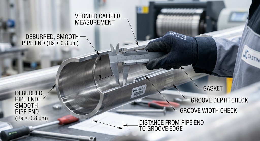
For grooved pipes, measure the groove depth and width with a vernier caliper.
As a general control point from the original requirements:
- Pipes below DN100: dimensional error within ±0.1 mm
- Pipes above DN200: dimensional error within ±0.2 mm
The actual tolerance must always follow the applicable standard, drawing, and connection system.
For pipe-end squareness, use a square or suitable measuring tool. Do not rely only on visual inspection.
5.3 Confirm Connection Sealing
Dimensional inspection is not the final step.
After the stainless steel clamp connection is assembled, perform a hydrostatic pressure test or air-tightness test when required by the system specification.
The test helps confirm that the finished connection has no leakage.
6. Common Pipe Cutting Errors and How to Prevent Them
Many clamp connection problems start during pipe preparation. The clamp itself may be correct, but an incorrect pipe cut can still cause connection failure.
6.1 Groove Too Deep or Too Shallow
A groove that is too deep can reduce the effective wall thickness and weaken the pipe.
A groove that is too shallow may prevent the clamp housing from engaging the pipe correctly.
The solution is to set the roll grooving machine stop according to the required groove depth.
As a process control method, inspect one pipe for every five pipes produced.
6.2 Pipe End Is Not Square
An angled cut is especially harmful to press-fit connections.
The sealing ring may not receive even pressure. This can increase the risk of leakage and premature seal wear.
Before cutting, secure the pipe with a suitable fixture. After cutting, check the end with a square.
If the cut is outside the required tolerance, cut the pipe again rather than trying to correct a major error during assembly.
6.3 Burrs Are Left on the Pipe End
Burrs can damage the sealing ring during insertion.
They can also become a source of metal particles. This is more serious in food, pharmaceutical, and other clean piping systems.
Remove burrs immediately after cutting. Use a deburring tool or suitable sandpaper.
For critical applications, an inspection camera can also be used to check the inner pipe wall.
7. Practical Checklist for Stainless Steel Clamp Pipe Cutting
Before installing the clamp, confirm the following points:
- The pipe is cut to the required length.
- The pipe end is straight and properly aligned.
- Burrs and sharp edges have been removed.
- The pipe has no visible cracks or deformation.
- The pipe roundness is acceptable.
- The groove position is correct for grooved connections.
- Groove depth and width meet the required dimensions.
- The groove surface is smooth and free from major defects.
- The insertion depth is marked for press-fit connections.
- The hose clamp size matches the pipe or hose outside diameter.
- The clamp is installed at the correct position.
- The completed connection passes the required leak test.
This simple inspection process can prevent many installation problems before the piping system is put into service.
In Short
There is no single pipe-end dimension that applies to every stainless steel clamp connection.
The correct stainless steel clamp pipe cut standards depend on the connection type, pipe diameter, and application requirements.
For grooved clamp connections, groove depth, groove width, groove position, and concentricity are the main control points.
For press-fit connections, pipe-end squareness, smoothness, insertion depth, and pipe roundness are more important.
For hose clamp connections, a clean cut, correct alignment, and proper clamp size help maintain a reliable connection.
Special industries may require additional controls. These can include Ra ≤ 0.8 μm or Ra ≤ 0.4 μm surface roughness, passivation, clean assembly, and tighter groove tolerances.
Using the correct cutting method and checking critical dimensions during production can reduce leakage, sealing problems, and premature connection failure.
Custom Stainless Steel Clamp Components from JC Casting
The pipe preparation is only one part of a reliable clamp connection. The quality and dimensional accuracy of the clamp components are also important.
JC Casting supplies stainless steel clamp components and custom metal parts for industrial piping applications. Our capabilities include material selection, casting, CNC machining, surface finishing, and dimensional inspection based on customer drawings and specifications.
If you need custom stainless steel clamps or related components, send us your drawings, dimensions, material requirements, or application details. Our engineering team can review your requirements and provide a suitable manufacturing solution and quotation.